Sie sind mit kostspieligen Ausfallzeiten konfrontiert, wenn handelsübliche Schläuche unter extremer Hitze oder Druck versagen. Wie können Sie einen Schlauch garantieren, der genau Ihren Spezifikationen entspricht und zuverlässig funktioniert? Der kundenspezifische Silikonschlauch-Prozess bietet eine kollaborative Lösung vom Konzept bis zum fertigen Produkt. Das Verständnis dieses Prozesses versetzt Sie in die Lage, fundierte Entscheidungen zu treffen. Kundenspezifische Silikonschläuche halten bei richtiger Verstärkung 10–15 Jahre, anstatt der üblichen 3–5 Jahre bei Gummischläuchen.
Kundenspezifische Silikonschläuche mit richtiger Verstärkung halten 10 bis 15 Jahre. Gummischläuche halten nur 3 bis 5 Jahre.
Definieren Sie Ihre Anforderungen an Medium, Temperatur und Druck präzise. Dies verhindert Schlauchversagen und kostspielige Ausfallzeiten.
Wählen Sie die richtige Silikonqualität und die passenden Anschlüsse für Ihre Umgebung. Dies sorgt für eine perfekte Passform und eine lange Lebensdauer.
Bevor Sie einen Hersteller kontaktieren, müssen Sie Ihre Anwendungsanforderungen präzise definieren. Dieser grundlegende Schritt bestimmt jede nachfolgende Entscheidung im Prozess für kundenspezifische Silikonschläuche. Das Überspringen dieser Analyse führt zu vorzeitigem Versagen, kostspieligen Neukonstruktionen und betrieblichen Ausfallzeiten. Sie benötigen einen systematischen Ansatz, um den gesamten Betriebsbereich Ihres Systems zu erfassen.
Das Medium, das Ihr Schlauch transportiert, bestimmt die Materialzusammensetzung. Sie müssen die genaue chemische Zusammensetzung, Konzentration und Temperatur des Mediums am Kontaktpunkt identifizieren. Silikon weist eine hervorragende Beständigkeit gegenüber gängigen Kühlmitteln auf, einschließlich Ethylenglykol, Propylenglykol, organischer Säuretechnologie (OAT) und hybriden OAT-Formulierungen. Diese Medien erhalten die strukturelle Integrität und Flexibilität des Silikons ohne Beeinträchtigung.
Kompatibilitätsprobleme treten jedoch auf, wenn Sie Silikon mit inkompatiblen Medien kombinieren. Standard-Motoröl ohne Fluorsilikon-Auskleidung führt dazu, dass Silikon aufquillt und schließlich reißt. Längere Einwirkung von hochintensiven UV-Strahlen oder Ozon erzeugt „Ozonrisse“, die als kleine spinnennetzartige Risse auf der Schlauchoberfläche erscheinen. Sie müssen immer überprüfen, ob Ihr Schlauchmaterial für die spezifischen Chemikalien, die es transportieren soll, zugelassen ist.
Die Folgen einer unzureichenden Identifizierung des Mediums erweisen sich als schwerwiegend:
Chemischer Abbau: Inkompatible Medien zersetzen das Schlauchmaterial auf molekularer Ebene, was zu Schwächung, schleichenden Lecks und schließlich zum Platzen führt.
Quellung und Verschlechterung: Schlauchmaterialien absorbieren Medienbestandteile, was den Innendurchmesser verringert, den Durchfluss und Druck beeinträchtigt und zu Rissen, Spalten und Versagen führt.
Schlauchversagen: Plötzlicher, unvorhersehbarer Verlust der hydraulischen Leistung, Maschinenschäden und Sicherheitsrisiken für das Personal.
Der Kontakt mit einer inkompatiblen Chemikalie kann zu Quellung, Erweichung, Verhärtung, Rissbildung, Verfärbung, Permeation, Verlust der Flexibilität, Trennung zwischen den Schlauchschichten, Lecks oder plötzlichem Versagen führen. Die Kompatibilität ändert sich auch mit Temperatur und Konzentration. Ein Material, das für eine verdünnte Chemikalie bei Raumtemperatur sicher ist, kann bei einer konzentrierten Lösung bei erhöhten Temperaturen versagen.
Sie sollten sich auf etablierte Prüfnormen beziehen, um die Materialverträglichkeit zu validieren. Die folgende Tabelle skizziert die primären Methoden, die Hersteller verwenden:
|
Norm/Prüfverfahren |
Beschreibung |
|---|---|
|
ISO 1817 |
Internationale Norm zur Bewertung der Materialverträglichkeit mit Medien, die Eintauchdauer, Temperaturbedingungen und Medienzusammensetzungen definiert. |
|
ASTM D471 |
Standardprüfverfahren für Gummieigenschaften – Wirkung von Flüssigkeiten, einschließlich der Messung von Volumenquellung und anderen Eigenschaftsänderungen. |
|
SAE J200 |
Klassifizierungssystem für Gummimaterialien, das Anforderungen an Medienbeständigkeit und Leistung enthält. |
|
Messung der Volumenquellung |
Gravimetrische Analyse nach dem Eintauchen bei erhöhten Temperaturen (23 °C bis 150 °C), um die prozentuale Volumenzunahme zu quantifizieren. |
|
Erhalt der Zugfestigkeit (ASTM D412) |
Misst die Fähigkeit, die mechanische Integrität nach Medienkontakt aufrechtzuerhalten, durch Vergleich der Zugfestigkeit vor und nach der Einwirkung. |
|
Härteänderung (ASTM D2240) |
Durometer-Prüfung zur Verfolgung von Shore-A-Härteänderungen, was auf Weichmacherentzug oder Polymervernetzung hinweist. |
|
Druckverformungsrest (ASTM D395 Methode B) |
Bewertet die elastische Erholung nach längerer Kompression in Medienumgebungen, um Klemm- und Anschlussbedingungen zu simulieren. |
|
Medienbeständigkeitsprüfung |
Protokolle zur beschleunigten Alterung, die Temperaturwechsel und chemische Einwirkung kombinieren, um den langfristigen Abbau vorherzusagen. |
|
FTIR (Fourier-Transformations-Infrarotspektroskopie) |
Fortschrittliches analytisches Verfahren zur Erkennung von Veränderungen der chemischen Struktur nach Flüssigkeitseinwirkung. |
|
DSC (Dynamische Differenz-Kalorimetrie) |
Misst Änderungen der thermischen Eigenschaften, wie z. B. Verschiebungen der Glasübergangstemperatur, aufgrund von Flüssigkeitsinteraktion. |
Sie müssen sowohl die maximalen als auch die minimalen Temperaturen dokumentieren, denen Ihr Schlauch während des Dauerbetriebs und bei kurzzeitigen Spitzen ausgesetzt ist. Silikon bietet im Vergleich zu anderen Elastomeren eine außergewöhnliche thermische Stabilität. Die folgende Tabelle zeigt die typischen Temperaturbereiche für kundenspezifische Silikonschläuche:
|
Expositionsart |
Temperaturbereich |
|---|---|
|
Dauerbetrieb |
-60°C bis 260°C (-76°F bis 500°F) |
|
Kurzzeitige Einwirkung |
Bis zu 315°C (600°F) |
Eine genaue Temperaturdefinition verhindert Sprödigkeit, Rissbildung und Materialschwächung durch extreme Hitze oder Kälte. Zum Beispiel SUNRISE Schläuche arbeiten von -50°F bis 212°F und erfordern eine Akklimatisierung vor dem Gebrauch. Sie müssen auch Umgebungstemperaturschwankungen berücksichtigen, die den Schlauch beeinflussen, selbst wenn die Flüssigkeit ungenutzt im System steht.
Druckanforderungen erfordern die gleiche Aufmerksamkeit. Sie müssen den maximalen Betriebsdruck, den Spitzendruck und die Vakuumbedingungen angeben, denen Ihr System ausgesetzt ist. Die Verstärkungsschicht Ihres Schlauches entspricht direkt diesen Druckanforderungen:
|
Druckbedingung |
Erforderliche Verstärkung |
|---|---|
|
Hoher Druck |
Gewickelte Schläuche (Berstdruck = 4x Betriebsdruck) |
|
Vakuum |
Verstärkter Schlauch (Metalldraht) zur Vermeidung von Kollaps |
Für Hochdruckanwendungen in Automobil- oder Hydrauliksystemen sollten Sie verstärkte Silikonschläuche mit zusätzlichen Schichten verwenden, um erhöhte Drücke sicher zu bewältigen. SUNRISE Schläuche haben ein Minimum von 500 PSI und einen Sicherheitsfaktor von 3:1, aber Sie müssen den Druck je nach Aufgabe anpassen.
Hydraulikschläuche dürfen nicht bei Drücken betrieben werden, die ihre ausgelegten Betriebsdruckgrenzen überschreiten, und Standardschläuche sollten keinen Temperaturen außerhalb von -40°C bis +120°C ausgesetzt werden. Der Betrieb außerhalb dieser Grenzen reduziert die Lebensdauer direkt; für extreme Bedingungen sind Spezialschläuche erforderlich.
Das Verhältnis zwischen Temperatur und Druck ist entscheidend. Hohe Temperaturen verringern die Zugfestigkeit des Schlauchmaterials, was dessen Druckstufe senkt. Sie müssen beide Faktoren gleichzeitig bewerten, nicht unabhängig voneinander.
Ihre Betriebsumgebung bringt Variablen jenseits von Flüssigkeit und Druck mit sich. Sie müssen UV-Exposition, Ozonkonzentration, chemische Dämpfe, Abriebquellen und physische Installationsbeschränkungen bewerten. Diese Faktoren beeinflussen die Materialauswahl und die Schlauchführung erheblich.
|
Umweltfaktor |
Auswirkung auf Silikonschläuche |
|---|---|
|
Ultraviolettes (UV) Licht |
Längere Einwirkung führt dazu, dass Gummi spröde wird und mit der Zeit abbaut; wichtig für Außenanwendungen mit direktem Sonnenlicht. |
|
Ozon |
Einwirkung führt dazu, dass Gummi spröde wird und reißt; Ozon kann natürlich vorhanden oder künstlich erzeugt sein (z. B. durch Elektromotoren). |
Silikon zeigt eine bemerkenswerte Beständigkeit gegen Ozon- und UV-Abbau. Standardisierte Ozonbeständigkeitsprüfungen (ASTM D1149, ISO 1431) bei 50 pphm Ozon, 40°C und 20% Zugdehnung zeigen selbst nach 1.000 Stunden keine sichtbare Rissbildung im Silikonkautschuk, während Naturkautschuk innerhalb von 24 Stunden reißt. In wässrigen Umgebungen mit 10 ppm Ozon behielten Silikonkautschukfolien nach 10.000 Stunden kontinuierlicher Einwirkung über 90% ihrer Zugfestigkeit und über 85% ihrer Bruchdehnung bei, ohne Oberflächenverschlechterung. Dynamische Ozonprüfungen (50 pphm, 10% zyklische Dehnung bei 1 Hz) zeigen ebenfalls keine Rissbildung nach 100 Stunden, was die chemische Stabilität des Si-O-Si-Rückgrats demonstriert.
Installationsfaktoren erfordern eine sorgfältige Messung des verfügbaren Platzes, der Leitungswege und der Biegeradiusbeschränkungen. Der minimale Biegeradius stellt die engste Kurve dar, die ein Schlauch ohne Beschädigung tolerieren kann. Sie müssen die Biegeradiusspezifikationen einhalten, um optimalen Systemdruck, Durchflusseffizienz und die allgemeine Langlebigkeit des Schlauches zu gewährleisten.
|
Auswirkungsmetrik |
Quantitative Auswirkung |
|---|---|
|
Reduzierung der Lebensdauer bei Unterschreitung des Mindestbiegeradius |
Bis zu 70% Reduzierung durch beschleunigte Ermüdung und strukturelle Schwächung |
|
Durchflussdrosselung pro 10 % Unterschreitung des empfohlenen Biegeradius |
Etwa 5-8 % Durchflussdrosselung und entsprechende Leistungsverluste |
Das Biegen eines Schlauchs über seinen empfohlenen Radius hinaus führt dazu, dass die interne Verstärkung bricht. Dies führt zum Kollabieren der Schlauchwand und zu einer Einschränkung des Durchflusses. Die resultierende Drosselung kann zu Lecks, Rissen oder Verunreinigungen führen, insbesondere in sensiblen Anwendungen wie der Lebensmittel-, Getränke- und Pharmaindustrie. Das Überschreiten des minimalen Biegeradius kann auch zu Knicken führen, was den Durchfluss weiter einschränkt und den Druckabfall erhöht. Diese Probleme können zu Rissen oder zum Aufplatzen der Schlauchwand, Schäden an internen Verstärkungen und einer Verringerung der Druckkapazität führen, was letztendlich ungeplante Ausfallzeiten, Produktverluste und Sicherheitsvorfälle zur Folge hat.
Die Einhaltung der Biegeradius-Spezifikationen ist entscheidend für die Aufrechterhaltung eines optimalen Systemdrucks, der Durchflusseffizienz und der allgemeinen Langlebigkeit des Schlauchs. Mit der Zeit kann eine unsachgemäße Verlegung zu Rissen und katastrophalem Schlauchversagen führen. Eine ordnungsgemäße Verlegung verlängert nicht nur die Lebensdauer des Schlauchs, sondern verbessert auch die Systemeffizienz und die Sicherheit des Bedieners.
Sie sollten bei der Installation auch Vibrationen, Biegehäufigkeit und potenzielle Abriebstellen berücksichtigen. Jeder Faktor schränkt Ihre Materialoptionen ein und beeinflusst die Verstärkungsstrategie. Eine gründliche Dokumentation dieser Anforderungen zu Beginn rationalisiert den gesamten Prozess für kundenspezifische Silikonschläuche und verhindert kostspielige Überarbeitungen zu einem späteren Zeitpunkt.
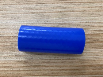
Nachdem Sie Ihre Anwendungsanforderungen definiert haben, gehen Sie zur Materialauswahl über. Diese Phase verwandelt Ihre Spezifikationen in ein konkretes Schlauchdesign. Sie wählen die Silikonqualität, Abmessungen, Härte, Farbe und Endanschlüsse. Jede Entscheidung beeinflusst Leistung, Haltbarkeit und Kosten. Das Verständnis dieser Optionen hilft Ihnen, den Prozess für kundenspezifische Silikonschläuche sicher zu steuern.
Silikon ist kein einzelnes Material. Es gibt viele Qualitäten, die jeweils für spezifische Bedingungen entwickelt wurden. Sie müssen die Qualität auf Ihre Betriebsumgebung abstimmen. Die folgende Tabelle zeigt die gängigsten Silikonqualitäten und ihre wichtigsten Unterscheidungsmerkmale.
|
Qualitätsbezeichnung |
Typ |
Wichtige Unterscheidungsmerkmale |
|---|---|---|
|
AMS 3195 Mittlerer Silikonschwamm |
Schwamm |
Mittlere Dichte, kontrollierte Kompression, wetterbeständig |
|
AMS 3196 Fester geschlossenzelliger Silikonschwamm |
Schwamm |
Feste Dichte, starker Dichtungsdruck, langlebig |
|
ASTM D1056 Weicher Silikonschwamm |
Schwamm |
Weich, flexibel, hervorragende Polsterung |
|
Handelsüblicher Silikonschwamm |
Schwamm |
Kosteneffizient, vielseitige Abdichtung |
|
Massives FDA-konformes Weiß |
Massiv |
Lebensmittelecht, hygienisch, hitzebeständig |
|
Elektrisch leitfähiges Silikon |
Massiv |
EMI/RFI-Abschirmung, statische Kontrolle |
|
Glasfaserverstärktes Silikon |
Massiv |
Hohe Reißfestigkeit, Dimensionsstabilität |
|
AA-59588 / ZZ-R-765 Qualität |
Massiv |
Luft- und Raumfahrt/militärisch zertifizierte Leistung |
|
UL 94 HB Flammhemmender Schwamm |
Schwamm |
Grundlegende Flammwidrigkeit |
|
UL 94 V-0 Flammhemmender Schwamm |
Schwamm |
Selbstverlöschend, raucharm, höchste Brandsicherheit |
|
RMA-Präzisionstoleranzklassen |
Standard |
Genaue Abmessungen, hohe Wiederholgenauigkeit |
Ihre Branche bestimmt die geeignete Qualität. Berücksichtigen Sie diese gängigen Anwendungen:
Medizin & Pharmazie: Verwendet festes FDA-konformes weißes Silikon, ASTM D1056 weichen Silikonschwamm und AA-59588/ZZ-R-765-Qualität für Reinheit, Biokompatibilität und Sterilisationsstabilität.
Lebensmittel- & Getränkeverarbeitung: Verwendet festes FDA-konformes weißes Silikon und geschlossenzellige Schwammqualitäten (AMS 3195/3196) für Hygiene und Hitzebeständigkeit.
Automobil- & EV-Systeme: Verwendet AMS 3195/3196, glasfaserverstärktes Silikon und AA-59588/ZZ-R-765 für Hitzestabilität und Langlebigkeit.
Luft- & Raumfahrt sowie Verteidigung: Verwendet UL94 V-0 flammhemmenden Schwamm, AA-59588/ZZ-R-765 und glasfaserverstärktes Silikon für Brandsicherheit und zertifizierte Leistung.
Elektronik & Elektrotechnik: Verwendet elektrisch leitfähiges Silikon und UL94 HB/V-0-Qualitäten für EMI/RFI-Abschirmung und Flammwidrigkeit.
Industriemaschinen: Verwendet AMS 3196 festen Schwamm, kommerziellen Schwamm und verstärktes festes Silikon für kontinuierliche Hitze- und Druckbelastung.
Bauwesen: Verwendet weiche bis mittlere Schwammqualitäten und kommerzielles Silikon für Wetterabdichtungen und Haltbarkeit im Außenbereich.
Die mechanischen Eigenschaften variieren ebenfalls je nach Qualität. Sie müssen die Dehnung und Reißfestigkeit für Ihre Anwendung bewerten. Die folgende Tabelle zeigt typische Bereiche für die verschiedenen Silikonqualitätskategorien.
|
Silikonqualitätskategorie |
Dehnungsbereich |
Reißfestigkeitsbereich |
|---|---|---|
|
Allzweckkautschuke |
100–1.100 % |
5–55 N/mm |
|
Weich bis mittelhart |
500–800 % |
10–30 N/mm |
|
Hochfeste Spezialqualität |
400–700 % |
30–55 N/mm |
Eine hochfeste Spezialqualität bietet eine geringere Dehnung, aber eine überlegene Reißfestigkeit. Diese Kombination eignet sich für Anwendungen mit wiederholter Biegung oder hoher mechanischer Belastung. Eine weiche Qualität bietet eine größere Dehnbarkeit, aber eine geringere Reißfestigkeit. Wählen Sie das Gleichgewicht, das Ihren Betriebsbedingungen entspricht.
Sie müssen die genauen Abmessungen Ihres Schlauchs angeben. Länge, Innendurchmesser und Wandstärke definieren die Schlauchgeometrie. Diese Abmessungen müssen die Durchflussrate, den Druckabfall und den Einbauraum Ihres Systems berücksichtigen. Der Hersteller fertigt Schläuche nach Ihren präzisen Maßen und sorgt so für eine perfekte Passform.
Der Härtegrad misst die Härte des Silikonmaterials. Diese Eigenschaft beeinflusst direkt die Flexibilität und Abriebfestigkeit. Die folgende Tabelle veranschaulicht den Zusammenhang.
|
Härtegrad (Shore A) |
Flexibilität |
Abriebfestigkeit |
|---|---|---|
|
Niedrig (z. B. 10–40) |
Hoch – passt sich leicht an, gut für Dichtungen und Komfort |
Niedrig – kann unter hoher Kompression oder Abrieb reißen oder versagen |
|
Mittel (z. B. 50–60) |
Ausgewogen – bietet moderate Flexibilität und Zähigkeit |
Moderat – geeignet für allgemeine Anwendungen |
|
Hoch (z. B. 70–80) |
Niedrig – widersteht Verformung, weniger flexibel |
Hoch – widersteht physischem Abrieb und Extrusion |
Eine geringe Härte (20–40 Shore A) eignet sich gut für Dichtungsanwendungen, bei denen sich der Schlauch unregelmäßigen Oberflächen anpassen muss. Eine hohe Härte (70–90 Shore A) eignet sich für Hochdrucksysteme, bei denen der Schlauch Verformung und Verschleiß widerstehen muss. Eine mittlere Härte bietet eine ausgewogene Option für die meisten allgemeinen Anwendungen.
Die Farbauswahl bietet sowohl funktionale als auch ästhetische Vorteile. Standard-Farboptionen helfen bei der Identifizierung von Flüssigkeitstyp und Systemfunktion.
Blau oder Grün: Weist typischerweise auf Kühlmittel- oder Heizungsschläuche hin.
Rot: Signalisiert häufig Getriebeöl- oder Servolenkungsflüssigkeitsschläuche.
Schwarz: Die häufigste Farbe für Kraftstoffschläuche, Vakuumleitungen und Mehrzweck-Gummischläuche.
Gelb oder Orange: Häufig für Klimaanlagen- oder Kältemittelleitungen verwendet.
Klar oder Transluzent: Zu finden an Kraftstoffleitungen oder Schläuchen von Emissionssystemen, bei denen eine visuelle Inspektion wichtig ist.
Wichtigste Erkenntnis: Die Farbe ist eine sekundäre Kennzeichnung. Die tatsächliche Kennzeichnung ist fast immer direkt auf dem Schlauch aufgedruckt (z. B. SAE-Standard, Material, Druckstufe). Verlassen Sie sich niemals allein auf die Farbe; ein blauer Silikonschlauch kann Kühlmittel, Luft oder Vakuum führen. Überprüfen Sie vor der Installation immer den vorgesehenen Verwendungszweck des Schlauchs.
Die Endarmaturen verbinden Ihren Schlauch mit dem System. Sie müssen den richtigen Typ für Ihre Anwendung auswählen. Zu den gängigen Optionen gehören Camlock- und Tri-Clamp-Armaturen.
Camlock-Armaturen bieten ein schnelles Verbinden und Trennen. Sie schieben den Schlauch auf den Vateradapter und verriegeln ihn mit den Hebelarmen. Anwendungsbereiche, die häufige Schlauchwechsel oder Reinigungen erfordern, profitieren von dieser Konstruktion. Camlock-Armaturen sind in verschiedenen Größen und Materialien erhältlich, einschließlich Edelstahl und Messing.
Tri-Clamp-Armaturen bieten eine sanitäre Verbindung. Sie klemmen den Schlauch mit einer Dichtung zwischen zwei Klemmstutzen ein. Diese Konstruktion eliminiert Spalten, in denen sich Bakterien vermehren können. Tri-Clamp-Armaturen dominieren in Lebensmittel-, Getränke-, Pharma- und Bioprozessanwendungen. Sie halten wiederholten Sterilisationszyklen ohne Leistungsabfall stand.
Weitere gängige Arten von Endarmaturen sind:
Flanscharmaturen: Für Hochdrucksysteme, die eine Verschraubung erfordern.
Schlauchbandarmaturen: Für Niederdrucksysteme, bei denen der Schlauch über die Tülle geschoben und festgeklemmt wird.
Schnellkupplungen: Für Anwendungen, die eine schnelle, werkzeuglose Verbindung erfordern.
NPT-Gewindearmaturen: Für Standard-Rohrgewinde-Verbindungen in industriellen Systemen.
Sie müssen überprüfen, ob das Material der Armatur mit Ihrem Medium und der Betriebstemperatur kompatibel ist. Edelstahl eignet sich für die meisten Anwendungen. Messing eignet sich für Systeme mit niedrigeren Temperaturen. Kunststoffarmaturen bieten Kosteneinsparungen für unkritische Anwendungen.
Die Auswahl der richtigen Endarmatur sorgt für eine leckfreie Verbindung und verlängert die Lebensdauer Ihres Schlauchs. Der gesamte Prozess zur Herstellung maßgeschneiderter Silikonschläuche hängt davon ab, dass diese finale Spezifikation mit den Schnittstellenanforderungen Ihres Systems übereinstimmt.
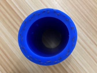
Sie müssen Ihren Silikonschlauch verstärken, wenn der Betriebsdruck die natürlichen Grenzen des Materials überschreitet. Die Verstärkungsschicht bestimmt die Druckkapazität und die strukturelle Integrität Ihres Schlauchs. Jedes Material bietet spezifische Vorteile für bestimmte Anwendungen.
|
Verstärkungsmaterial |
Temperaturbereich |
Hauptvorteil |
Haupteinsatzgebiet |
|---|---|---|---|
|
Polyester |
-54°C bis 177°C |
Kostengünstig, flexibel |
Standard-Kühlmittel-/Heizungsschläuche |
|
Aramid (Nomex®) |
-54°C bis 260°C |
Hochtemperaturbeständigkeit, Beständigkeit gegen Vibrationsermüdung |
Turbolader, Ladeluftkühler, AGR-Systeme |
|
Glasfaser |
-54°C bis 260°C |
Hochtemperaturbeständigkeit |
Hochtemperatur-Luft-/Abgasführung |
|
Edelstahldraht |
-54°C bis 260°C |
Vakuumfestigkeit, knickfest, hoher Druck |
Vakuum-/Saugleitungen, Hochdruckanwendungen |
Meta-Aramid-Verstärkung wird gewählt, wenn Schläuche bei hohen Temperaturen eingesetzt werden, aggressiven Kühlmitteln ausgesetzt sind und zunehmend anspruchsvolleren Druckzyklen standhalten müssen. Im Gegensatz dazu brennen Polyester- oder gemischte Meta-Aramid-Gewebe leichter und bieten unter strengen Bedingungen nicht das gleiche Maß an Feuerbeständigkeit oder mechanischer Leistung.
Polyestergeflecht bewältigt die meisten Standardanwendungen mit ausreichender Flexibilität und geringeren Kosten. Aramidfaser hält höheren Ladedrücken und längerer Hitzeeinwirkung stand, was sie zur überlegenen Wahl für anspruchsvolle Umgebungen macht. Ihre Betriebsbedingungen bestimmen, welche Verstärkung Sie wählen.
Sie wählen zwischen zwei primären Fertigungsmethoden basierend auf Ihrer Schlauchgeometrie und Ihrem Produktionsvolumen. Die Extrusion erzeugt kontinuierliche Profile mit konstantem Querschnitt, ideal für Standardrohre und Kühlmittelleitungen. Die Formgebung erzeugt komplexe Formen mit unregelmäßigen Geometrien, Biegungen und integrierten Anschlüssen.
|
Attribut |
Spritzguss |
Extrusion |
|---|---|---|
|
Herstellbare Geometrie |
Unregelmäßige/komplexe Rohre |
Reguläre Rohre (konstanter Querschnitt) |
|
Rohmaterialzustand |
Flüssigsilikon (transparent) |
Festes Silikon (verdichtet/erweicht) |
|
Härte |
Weicher (geringere Härte) |
Härter (30-75°) |
|
Transparenz |
Höhere Transparenz |
Geringere Transparenz |
|
Kosten |
Höher (Rohmaterialien, Ausrüstung) |
Niedrigere Kosten für Standard-Rohrleitungen |
Formgepresste Schläuche bieten engere Toleranzen und glattere Innenflächen, wodurch Turbulenzen und Kontaminationsrisiken minimiert werden. Extrudierte Schläuche bieten kostengünstige Lösungen für die Produktion in großen Mengen. Die Präzisionsanforderungen und das Budget Ihrer Anwendung bestimmen die geeignete Methode.
Sie müssen sicherstellen, dass Ihr Prozess für kundenspezifische Silikonschläuche umfassende Qualitätssicherungsprotokolle beinhaltet. Durch Tests wird validiert, dass Ihr Schlauch die Spezifikationen erfüllt und unter realen Bedingungen zuverlässig funktioniert.
Prüfung der Maßhaltigkeit
Druckprüfung (einschließlich Überprüfung der Berstfestigkeit)
Dichtheitsprüfungen
Flexibilitätsprüfung
Prüfung der Maßtoleranz
Vakuumtests stellen sicher, dass Ihr Schlauch seine strukturelle Integrität unter Unterdruck beibehält. Sie schließen den Schlauch an eine Vakuumpumpe an, reduzieren den Innendruck schrittweise und überwachen ihn auf Verformungen oder Lecks. Dieser Prozess identifiziert Schwachstellen und potenzielle Fehlerpunkte vor der Installation.
Der Prozess für kundenspezifische Silikonschläuche gipfelt in einer Zertifizierung, die die Leistungsmerkmale Ihres Schlauchs dokumentiert. Diese Dokumentation bietet Rückverfolgbarkeit und Vertrauen für Ihr gesamtes System.
Sie verstehen nun den Prozess für kundenspezifische Silikonschläuche: Anforderungen definieren, Materialien auswählen, Design anpassen und Qualität durch Tests verifizieren. Arbeiten Sie mit einem erfahrenen Hersteller zusammen, der Sie bei jedem Schritt begleitet. Arbeiten Sie mit einem Team, das Ihre individuellen Bedürfnisse versteht und einen Schlauch liefert, der auf Leistung ausgelegt ist. Ein gut konstruierter, kundenspezifischer Schlauch gewährleistet Sicherheit, Effizienz und Langlebigkeit für Ihr gesamtes System.
Sie können mit 4 bis 6 Wochen von der Designfreigabe bis zum Versand rechnen. Die Lieferzeiten variieren je nach Komplexität, Verstärkungsanforderungen und Materialverfügbarkeit.
Sie sollten Endstücke durch neue ersetzen. Die Wiederverwendung alter Anschlüsse gefährdet die Dichtungsintegrität und kann zu Lecks am Verbindungspunkt führen.
Die meisten Hersteller verlangen ein Minimum von 50 bis 100 Einheiten pro Design. Sie können geringere Mengen für Prototypen oder Vorserien verhandeln.

Sunrise Silicone Hose Co., Limited


Die Anschrift : Suite 805, No. 341 Jiahe Road, Xiamen City, Fujian Province, China
Email : sales@siliconehose-china.com